


Story
Almost every solar-based system has a battery associated with it that must be charged by the sun, and the energy from the battery is then used to drive the load.
The most popular choice is MPPT
Because in any situation, whether the sunlight conditions are good or bad, the MPPT charge controller uses this maximum power output factor and converts it into the optimal charging voltage and current for the battery.
This means that MPPT has an advantage that is different from other ordinary charge controllers. It can charge the battery even in poor sunlight.
Design features of MPPT
Can charge 2P2S battery (6.4-8.4V)
Charging current is 600mA
It will have an additional charging option using an adapter.
Supply
LT3652 Driver
1N5819-3 pcs
10kpot
10uF Capacitors - 2 pcs
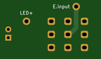
Green LED
Orange LED
220k resistor
330k resistor
200k resistor
68uH Inductor
1uF capacitor
100uF capacitor - 2 pcs
Battery-7.4V
1k resistors 2 pcs
Barrel socket
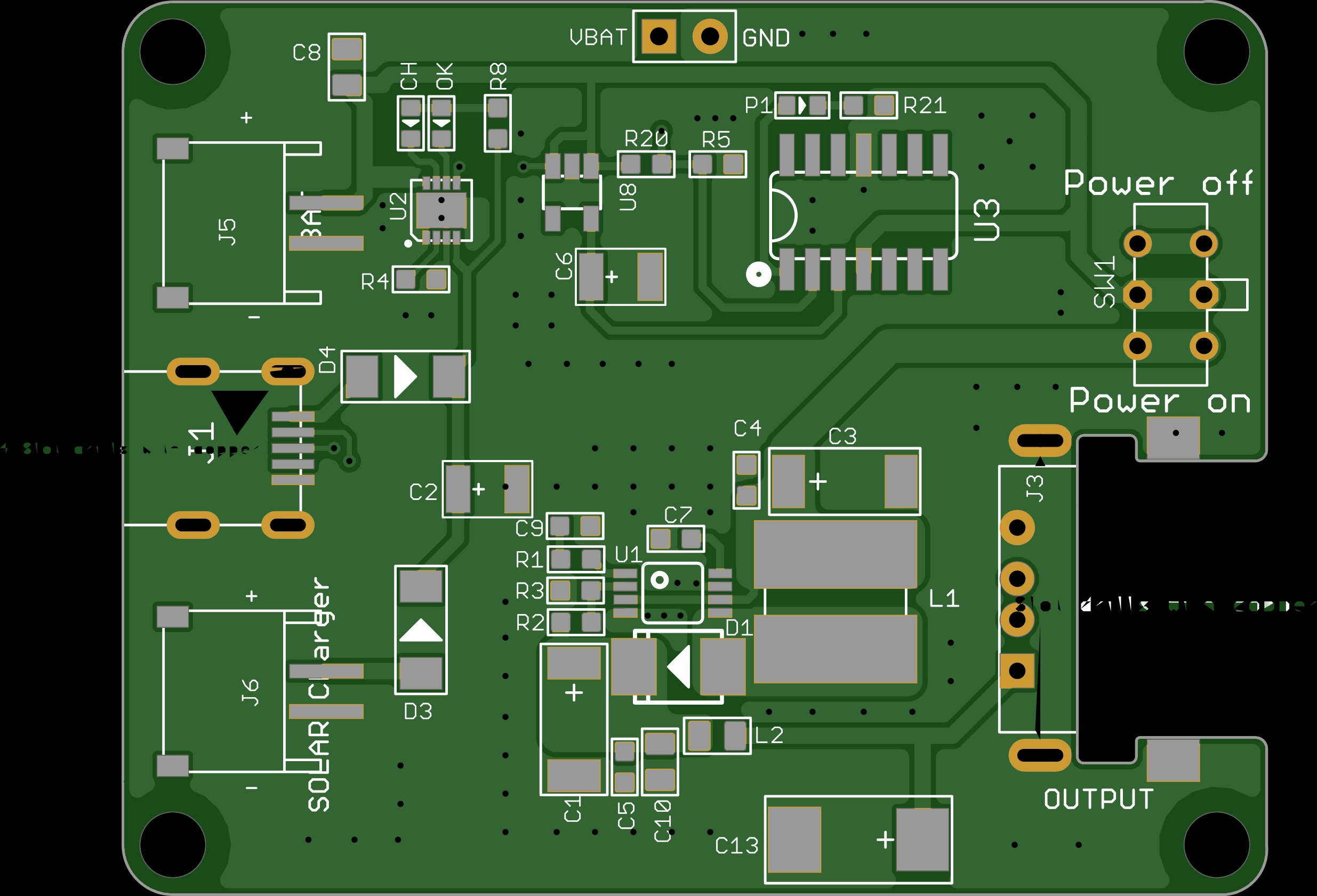
MPPT Solar Charger Circuit Diagram

The circuit uses LT3652 which is a complete monolithic step-down battery charger that operates over a 4.95V to 32V input voltage range. Thus, the maximum input range is 4.95V to the 32V for both solar and adapter. The LT3652 provides a constant current / constant voltage charge characteristics. It can be programmed through current sense resistors for a maximum of 2A charge current.
On the output section, the charger employs 3.3V float voltage feedback reference, so any desired battery float voltage up to 14.4V can be programmed with a resistor divider. The LT3652 also contains a programmable safety timer using a simple capacitor. It is used for charge termination after the desired time is reached. It is useful to detect battery faults.
The LT3652 requires MPPT setup where a potentiometer can be used to set the MPPT point. When the LT3652 is powered using a solar panel, the input regulation loop is used to maintain the panel at peak output power. From where the regulation is maintained depends on the MPPT setup potentiometer.
All these things are connected to the schematic. The VR1 is used to set the MPPT point. R2, R3, and R4 are used to set the 2S battery charging voltage (8.4V). Formula to set battery voltage can be given by-
RFB1 = (VBAT(FLT) • 2.5 • 105)/3.3 and RFB2 = (RFB1 • (2.5 • 105))/(RFB1 - (2.5 • 105))
The capacitor C2 is used to set up the charge timer. The timer can be set using the below formula-
tEOC = CTIMER • 4.4 • 106 (In Hours)
The D3 and C3 are the boost diode and boost capacitor. It drives the internal switch and facilitates the saturation of the switch transistor. The boost pin operates from 0V to 8.5V.
R5 and R6 are a current sense resistor connected in parallel. The charge current can be calculated using the below formula-
RSENSE = 0.1/ ICHG(MAX)
The current sense resistor in the schematic is selected 0.5 Ohms and 0.22 Ohms which is in parallel creates 0.15 Ohms. Using the above formula, it will produce almost 0.66A of charge current. The C4, C5, and C6 are the output filter capacitors.
The DC barrel jack is connected in such a way that the solar panel will get disconnected if an adapter jack is inserted into the adapter socket. The D1 will protect the solar panel or the adapter from reverse current flow during no charging condition.
Test
To test the circuit, a solar panel rated 18V .56A was used. The picture below is the detailed specifications of the solar panel.

Charging uses 2P2S battery (8.4V 4000mAH) battery. The entire circuit was tested under moderate sunlight conditions -

Once everything is connected, and when sunlight conditions are right, the MPPT is set and the potentiometer is controlled until the charging LED starts glowing. The circuit works smoothly
下面列表项
- aaa
- bbb
- ccc
没有了,呵呵